

Science makes it known,
Engineering makes it work,
Art makes it beautiful.
|
|
Lazarus Sub-form, Object Pascal, FORTRAN, Model Rocket Fins, and Glider Wings
A Lazarus sub-form is a form shown/used/called by a higher level form
using the sub-form's ShowModal method (calls sub-form's
FormShow(...)). The ShowModal method transfers
exclusive control to the sub-form.
Missle18 / FrmFinShpArea is a sub-form used in two Lazarus
multiform applications to input model rocket fin (MRmain) and
boost/glider wing/stabilizer (glider01) data; both fins and
wings/stabilizers are generalized as flight surfaces. Uses
TImage.Picture property, MessageDlg(...), QuestionDlg (...)
MRmain - model rocket (single and multi-stage; includes parallel stages)
data input and analysis (center of pressure, drag coefficient)
application (can be called in one of two modes - review and full input).
glider01 - Boost/Glider (example layout shown figure
below), Rocket/Glider, Lifting Body (lift generated by body shape; does not have wings,
may have stabilizers), and Rogallo FlexWing (three spars with thin film wing, arc
dihedral; hang gliders are a varient of Rogallo FlexWing) data input
application; restricted to single stage.

Missle18 / FrmFinShpArea refers to the rudder as
a Vertical Stabilizer
|
1
|
|
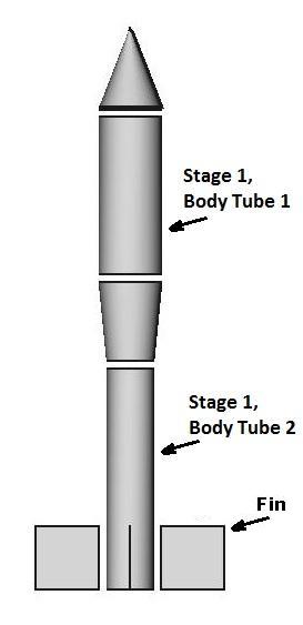
Simplified view of single stage
rocket with conical nose,
two body tubes, one conical
boattail, and four fins.
Indexing begins from nose tip.
|
Files:2
-
missle18.pas
- Fin/Wing Lazarus unit source file (class name TFrmFinShpArea); contains
user interface event procedures; calls
units/Librarys listed below for calculations and other data processing; has
{ public declarations } (glider specific variables)
- these can be accessed by other units by including missle18 in the
uses statement of the interface section (as long as it does
not cause a circular reference); has interface function isGlider ( )
called by another unit/sub-form.
missle18.lfm
- Fin/Wing/Stabilizer Sub-Form (FrmFinShpArea; shown below, has been modified slightly since initial upload)
aero021.inc
- include file used by missle18.pas, missle13.pas, aero020.pas;
glider related CONSTant (including TailType; see below) declarations
image3 files - representative fin/wing/stabilizer shape; uses predefined
shapes to aid data input (sub-form displays selected fin/wing
shape) and simplify calculations; when user selects Fin/Wing Shape,
the appropriate image file is loaded. These are:
Delta fin/wing
(right triangle)
Swept Delta
fin/wing (rear swept triangular)
Isosceles Triangle
fin/wing; equal length sides are fin/wing leading/trailing edges
General Triangle
fin/wing; not Delta, Swept Delta, nor Isosceles Triangle
Isosceles Trapezoid
fin/wing; parallel sides are root/tip, equal length sides are fin/wing
leading/trailing edges
Clipped Delta
fin/wing (Delta with tip clipped; geometrically trapezoid; root chord and
tip chord are parallel; shown below in screenshot - root chord on left, tip chord on right)
Tapered Swept3
fin/wing (rear swept trapezoid); root chord and tip chord are parallel
Rectangular
fin/wing
Elliptical
fin/wing (at maximum half ellipse); SemiSpan lies along semi-major axis;
semi-major axis perpendicular to fuselage axis;
ellipse symmetrical about semi-major axis
Elliptical Swept
fin/wing (rear swept); midchord (half-chord) lies along semi-major axis
Elliptical Clipped
fin/wing (half ellipse with tip clipped; root chord and tip chord
are parallel); SemiSpan lies along semi-major axis;
semi-major axis perpendicular to fuselage axis; Mean
Aerodynamic Chord (M.A.C., calculated in missle13.dll, see below)
approximation only for this shape
Elliptical Swept Clipped
fin/wing (rear swept half ellipse with tip clipped; root chord and tip chord
are parallel); half-chord lies along semi-major axis;
M.A.C. approximation only for this shape
Circular Vertical Stabilizer :
H-Tail vertical stablizers gliders only; this shape requires special
processing; attaches to either the main wing's or horizontal stabilizer's
tip. SemiSpan is the stabilizer's radius;
vertical stablizer's Length Fin/Wing Root
is the horizontal stabilizer's (or main wing) Length Fin/Wing Tip - where
the horizontal stabilizer (or main wing) attaches to the vertical stabilizer.
Compound
composed of two or more of the above shapes; shown for illustrative purposes only,
at present application requires basic fin/wing shape. If using a compound fin/wing,
will need to be simplified into one of the predefined fin/wing/stabilizer shapes,
as discussed 'TIR-33 Calculating the Center of Pressure', p. 10
|
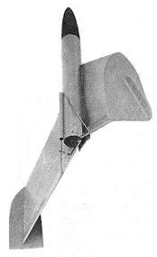
Space Plane Rocket/Glider;
Rocket/Gliders often use a
form of Variable Geometry
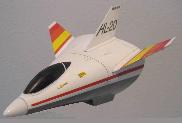
HL-20 Lifting Body
|
|
4
5
|
-
NumRecGlbl.pas
- Numerical Recipes6
global constants/variables/procedures Lazarus unit, reused in other Lazarus projects
& Object Pascal Librarys; has rudimentary data validation functions
genetyp.inc7
- include file developed from major rewrite of Dawkins8 Biomorphs;
contains useful CONSTant and TYPE declarations
nrtyp.inc
- Numerical Recipes include file; CONSTant and TYPE
declarations
-
missle24.pas (uses public declarations8) - model rocket
drag analysis Lazarus unit / sub-form (currently in development)
-
MRcommon.pas -
Model Rocket global constants/variables/procedures Lazarus unit; defines fin
data (most of the wing data is
stored in the fin data arrays (common to both model rockets and gliders); the
remainder (glider specific) in missle18.pas
{ public declarations }); calls procedures in
nrlazrs.dll
and missle02.dll
MRcommon global variable AirVhclTyp value determines whether
to process flight surface as a fin or wing/stabilizer
refer to source file comments for global variables' description;
MRcommon.pas is still being developed for
future sub-forms
missle.inc -
include file used by MRcommon.pas, aero020.pas, missle18.pas,
missle13.pas, and missle02.pas; rocket related
CONSTant and TYPE declarations
-
missle02.pas -
source code for Object Pascal Library missle02.dll (rocket related
functions/procedures); callable by Object Pascal
command console programs,
Object Pascal Windows programs, Lazarus, and indirectly D programs. Uses include files
genetyp.inc,
nrtyp.inc, and missle.inc; UOM conversion,
Error Message, compute glider/rocket components' surface area, overall rocket
cp/CNα,
and other functions/procedures; calls FORTRAN subroutines in mathproc.dll
and hwndio.dll (see below)
refer to source file comments for variables' description
missle02.dll - missle02.pas dynamic link library; compile with
fpcdll.bat
-
aero020.pas
- source code for Object Pascal Library aero020.dll (rocket & glider
related functions/procedures); also called by drag
analysis D Windows program. Uses include files genetyp.inc,
nrtyp.inc, missle.inc, and aero021.inc; fin/wing area
pre-processing
procedures, fin/wing plane area calculation, Boost/Glider & Rocket/Glider
file I/O, etc. Can call procedures in
hwndio.dll
(Object Pascal or D Windows main programs only), mathproc.dll, missle02.dll,
& missle13.dll
(uses unit missle06.pas)
aero020.dll - aero020.pas dynamic link library; compile with fpcdll.bat
-
FORTRAN Subprograms
(tir33.for
and mathaux.for)
extracted from
mathproc.for -
FORTRAN subroutines/functions to compute
basic shapes' surface area and rocket components' cp and
CNα; called by procedures
in missle02.dll, missle13.dll, & aero020.dll
mathproc.dll - mathproc.for dynamic link library; built using
SilverFrost FTN95 Plato IDE
Sub-form was originally designed for model rocket fins, adapted for glider wing/stabilizer/canard
usage, only basic
wings/stabilizers/canards measurements are enterable.
Fins are selected using Stage Number control (Stage 1 is the uppermost stage);
Wings/Stabilizers using Flight Surface control
(Main Wing, Horizontal Stabilizer, etc.). Model rocket
stage arrays are used to store fins/wings/stabilizers data.
When a new Fin/Wing/Stabilizer shape is selected, the Fin/Wing Shape
control's event procedure displays the appropriate
representative image, pre-loads as many Fin/Wing/Stabilizer
measurements as possible, and may "lock"/"unlock" some fields for input.
Also effects field editing and allowable values.
Unit variable TailType (set in main form) also effects allowable
values when entering data for Boost/Gliders, Rocket/Gliders, and
Lifting Bodies. For VTail, YTail, and TriFinTail tail
surfaces only, unit array variable Dihedral is used to measure angle of rotation
(measured in degrees, set in main form) from vertical axis (if TriFinTail
modeled as horizontal stabilizer and vertical stabilizer,
horizontal stabilizer Dihedral measured from horizontal axis).
|
9
|
Number of Fins / Wings
For model rockets10, the number of Fins / Stage (read only). Recommended values
are 3, 4, or 6 for compliance with
TIR-33 Calculating the Center of Pressure assumptions. Parallel Stages
usage may restrict to 3 or 4 fins on the nth (bottom) stage.
For gliders, this is the number of semi- Main Wings or Stabilizers (modifiable)
specified by Flight Surface control. A monoplane glider
has 2 semi- Main Wings, biplane has 4 (allowable value).
Body Radius is the distance from the Air Vehicle's longitudinal axis
to the Fin/Wing Root. Usually this is the body tube radius; for
boost/glider booms it is the equivalent radius of the boom's cross-sectional
area. For gliders, initially calculated by the calling program
when Body Radius = 0.0 (when semi-wings/stabilizers
mounted above/below fuselage with root chords touching, can input 0.0001 to
avoid calculation; will be displayed as 0.000);
can be modified. Body Radius is used in calculating interference drag.
Total wingspan = 2 * (Body Radius + SemiSpan)
(when using Circular Vertical Stabilizer, Body Radius
calculated in Missle18 / FrmFinShpArea event procedure
TFrmFinShpArea.FinShapeComboBoxClick(...))
Elliptical Minor Diameter (Root Chord for full half ellipse) and
Elliptical Major Radius (SemiSpan for full half ellipse) are
required if
elliptical fin has been clipped at either end.11 When clipped
at the tip, it is either an Elliptical Clipped or Elliptical Swept Clipped. When
clipped at the root end, calculations are accurate,
at the tip end, calculations are approximations.
Actual Length Midpoint Fin/Wing Root to Midpoint Fin/Wing Tip is the
length of a line from the midpoint Length Fin/Wing Root
to the Length Fin/Wing Tip. If Length Fin/Wing Tip = 0,
then it is the length of a line from the midpoint Length Fin/Wing Root to
the fin/wing/stabilizer/canard tip. For gliders, Quarter Chord
is treated similarly. Sub-form auto-calculates when possible; depending
on Fin/Wing Shape this may occur after entering SemiSpan,
Length Fin/Wing Tip, or Vertical 'Sweptback'.
File Commands:
- Calculate Fin Surface Area
calls aero020.dll procedure clippedFin1 (...), missle02.dll
function FlghtSrfcArea (...); depending on fin/wing shape, FlghtSrfcArea (...)
may call one or more functions in missle02.dll and/or mathproc.dll
- Close Form
sets ModalResult:=mrClose;
returns control to main form
Edit Commands (only available in Glider mode):
- Clear Canard Stab.
zeros CanardIndx element of fin/wing data arrays (constant defined
in aero021.inc)
- Clear Horz. Stab.
zeros HorzTailIndx element of fin/wing data arrays
- Clear Vert. Stab(s).
zeros VertTailIndx, VtailLindx, and VtailRindx
elements of fin/wing data arrays
Help Commands:
Implemented as simple ShowMessage (...) calls (focused on programs, not
relearning help files)
Many of the Sub-form fields have Hints
MRmain (model rocket application) event procedures invoking Missle18 / FrmFinShpArea:
TMRmain.BtnFinDesignClick(...) is the
full input mode (allows modifications), TMRmain.BtnFinShapeClick(...)
is the review mode (default). Missle18.unitMissle1110 and
Missle18.unitMissle18 are constants used to determine which mode.
glider01 uses a single event procedure, TmrGliderFrm.BtnFinDesignClick(...),
to invoke Missle18 / FrmFinShpArea in full input mode
Compiling / Linking :12
-
Compile and link FORTRAN mathproc.for
-
Compile and link FORTRAN sttstcs.for
- Open a MS-DOS Command Prompt13 and use batch file
fpcdll.bat
to compile the Object Pascal files
fpcdll hwndio
fpcdll nrlazrs
fpcdll missle02
fpcdll missle13
fpcdll aero020
- Start Lazarus (steps may vary depending on version)
New Project, Application
Project, New Project from File
select missle18.pas
View Forms
select FrmFinShpArea
click button Toggle Form/Unit (displays form)
add units NumRecGlbl.pas, MRcommon.pas
can add
untBT10
/
FrmBT10
and
missle14
/
FrmPayload
from Lazarus Body Tubes Sub-forms,
missle30
/
missle31
to start building your own model rocket analysis software system (MRmain) if desired.
To start building glider01, add
untBT10
/
FrmBT10
and
rg001.pas
/
rg001.lfm
At present, will need to supply your own version of
MRmain or glider01, and Missle11/Missle10 (if building
MRmain), missle24/missle25.
1. Mandell, Gordon. Technical Report TR-7 Front Engine Boost Gliders
2. Both MRmain and glider01 are large projects of over 25 source,
include, and form files. This is a partial list.
3. Some images from Barrowman, James.
TIR-33 Calculating the Center of Pressure;
NASA Glenn Research Center;
others created with A9CAD 2.2.1 and FreeCAD 0.012
4. Image from The Rocketry Forum. Space Plane was a kit originaly
available from Estes Rockets.
Space Plane is modeled with a TailType of HTail, due to outboard
vertical stabilizers mounted on the main wing.
5. Image from modelrocketbuilding.blogspot.com. HL-20 is a model rocket
lifting body kit originaly available from
Quest Model Rockets. Its flight control surfaces are an example of
a TriFinTail.
6. Press, William H., Brian P. Flannery, Saul A Teukolsky,
and William T. Vetterling (1986). Numerical Recipes: The Art of
Scientific Computing.
New York : Press Syndicate of the University of Cambridge. A
student version (in English) of Numerical
Recipes In 'C': The Art Of Scientific
Computing, Second Edition, © 1988-1992 is available from the
University of Trieste
at no cost.
7. Rietman, Edward (1994). Genesis Redux: Experiments Creating Artificial
Life. Windcrest (McGraw-Hill).
|
8. |
Missle25 - Drag Coefficient currently in development; glider01 uses
both { public declarations } and interface procedure;
Missle18 / FrmFinShpArea uses { public declarations }
Missle24/missle25 uses
missle30/missle31; Missle25 - Drag Coefficient includes
Parallel Stages (if any) in
CD calculations.
Missle24/missle25 is also used to input model rocket launch
conditions. The CD
calculation procedures are in
missle13.pas (link above). These yield
order of magnitude accuracy, though tend to be high, especially for
multi-stage
(both serial and parallel) rockets. These procedures are still being
refined. Many of the procedures can also be used
for Boost/Gliders and Rocket/Gliders.
|
9. Image from https://en.wikipedia.org/wiki/Empennage
and modified.
10. For model rockets (MRmain)
Missle11/Missle10 is used to enter stage data (Number of Stages,
Number of Fins/Wings,
and Linear Distance Reference Line to Root Edge),
can also be used to enter stage's fin measurements
11. Currently neither Elliptical Minor Diameter nor Elliptical Major Radius
values are retained between Stage Number
or Flight Surface changes. For elliptical clipped fins/wings/stabilizers/canards
it will be necessary to re-enter these values.
For Elliptical Swept Clipped at the root end, uses ELLIPSE_SEGMENT
algorithm from CALCULATING ELLIPSE OVERLAP
AREAS to calculate fin/wing/stabilizer area.
12. This is a complex project demonstrating as much re-use as possible of Librarys
from other projects, resulting in a
large compile/link list and multiple .dlls. For compatibility with
other programs, using 32 bit compilers.
13. Using 32-bit Command Prompt compilers for compiling Pascal .dll, D .dll, and D .exe
|
